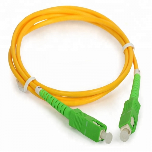
FIBER OPTIC PATCH CORD


Fiber Optic SC LC Patch Cord
Fiber Optic SC LC PATCH CORD
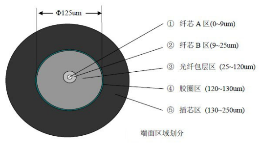
1. End face requirement:
1.1 Testing equipment: 400 × magnifying glass, display
1.2 Testing standard:
Geographic range | Defect description | End face detection standard |
Core A area | Scratch, gap | Not allowed |
Holes, spots | Not allowed | |
Dirty, foreign matter | Not allowed | |
‚ Core B area | Scratch, gap | Not allowed |
Holes, spots | Not allowed | |
Dirty, foreign matter | Not allowed | |
ƒ Optical cladding zone | Scratch, gap | Width ≦ 3um has one |
Holes, spots | Diameter ≦ 3um has one | |
Dirty, foreign matter | It is not allowed to be dirty. If it cannot be wiped, it is judged by holes. | |
④ Apron area | Scratch, gap | Width ≦ 20um has two |
Holes, spots | Diameter ≦ 20um has two | |
Dirty, foreign matter | It is not allowed to be dirty. If it cannot be wiped, it is judged by holes. | |
⑤ Ferrule area | Scratch, gap | Width ≦ 30um has two |
Holes, spots | Diameter ≦ 30um has two | |
Dirty, foreign matter | It is not allowed to be dirty. If it cannot be wiped, it is judged by holes. | |
Note: No cracks are allowed in the above areas, and the total defects are no more than 3 | ||
Figure 1
1.3 End face icon:
2. Standard test:
Product name | Insertion loss(IL) | Return loss(RL) | |
PC | SM | 0.25dm@1310um | 50dB@1310um |
MM | 0.25dm@850um | 45dB@850um | |
APC | SM | 0.25dm@1310um | 60dB@1310um |
Performance
Specification | |||||
Item | Unit | SM | MM | ||
SC/PC SC/UPC SC/APC | SC/PC | ||||
Insertion Loss | dB | ≤0.20 | |||
Max. Insertion Loss | dB | ≤0.30 | |||
Repeatability | dB | ≤0.10 | |||
Changeability | dB | ≤0.20 | |||
Return Loss | dB | 45 | 50 | 60 | |
Operation Temperature | ℃ | -25 ~ +70 | |||
Storage Temperature | ℃ | -40 ~ +85 | |||
Fiber type | um | 9/125 | 50/125,62.5/125 | ||
Core number | single or dual fiber | ||||
Durability | >1000 times | ||||
Industry Standard | Bellcore TA-NWT-001209 | ||||
2. 3D standard:
Pin outer diameter | Radius of curvature | Vertex offset | Light solder height | angle(。) | |
Ф2.5 | PC UPC type | 10~25 | ≤50 | -100~+50 | ------ |
APC type | 5~15 | ≤50 | -100~+50 | 8士0.3 | |
Ф1.25 | PC UPC type | 7~25 | ≤50 | -100~+50 | ------ |
APC type | 5~15 | ≤50 | -100~+50 | 8士0.3 | |
Note: In the numerical value of the column height, the positive sign indicates that the light solder is convex, and the negative sign indicates the light solder recess. ‚ PC pass rate is 70%, APC pass rate is 60%. | |||||
Figure 2
3. Package:
4.1 Winding:
ф1.8/2.0/3.0mm The optical cable is wound two times around one meter, wrapped with white wire, entangled with 5 meters and twisted twice and then knotted.
‚ ф0.9mm The optical cable is wound two times around one meter, and the serpentine tube is used. (The size of the serpentine tube is determined by the length of the cable, and the specification is 2.0/4.0mm.
4.2 Bag size:
Ф0.9 pigtail and ≦3M jumper with 18×18cm self-sealing bag (3.0 duplex 3M with 22×22cm ziplock bag)
‚ 22×22cm ziplock bag for ф1.8/2.0/3.0mm cable of 3M or more
ƒ All ziplock bags require white edges, and the bags need to be perforated. Each batch of punched holes should be in the same position.
4.3 Packing:
Ф0.9 is placed in a self-sealing bag of 18×18cm size per 1pcs, and the label is attached (the label is attached to the middle of the ziplock bag)
Each 10pcs bag is packed in a 22×22cm ziplock bag, and a cushion is placed on the upper and lower sides of the inner box to protect it.
Related Products
Fiber Optic SC LC Patch Cord